A Rock Core Drill is a specialized machine used to recover cylindrical samples from solid rock. These samples reveal geological layers hidden beneath soil, pavement, or weathered surfaces. Unlike destructive drilling, core drilling preserves a continuous record of the formation. That record supports mineral exploration, foundation studies, tunneling, and dam investigations.
The method is precise but physically demanding. A hollow diamond bit rotates against the rock while drilling fluid cools the bit and carries cuttings upward. As the barrel advances, intact rock enters the inner tube. Technicians then retrieve, clean, photograph, and log the core. A small fracture, color change, or mineral vein can influence an entire engineering decision. Sometimes, the core looks ordinary. It may still contain critical evidence.
Industry reports show why this work remains important. The USGS Mineral Commodity Summaries 2025 reports global copper mine production at approximately 23 million metric tons in 2024, sustaining demand for reliable exploration data. S&P Global Market Intelligence’s World Exploration Trends reports also track substantial annual spending on nonferrous mineral exploration. These figures do not prove that every drilling program will succeed. Ground conditions vary sharply.
ASTM D2113 provides recognized guidance for diamond core drilling and rock sampling practices. It emphasizes equipment selection, recovery measurement, and careful documentation. Experienced crews also watch penetration pressure, rotation speed, fluid loss, and core recovery. Poor recovery can distort geological interpretation. That limitation deserves attention. A Rock Core Drill is powerful, but it is not infallible. Its results depend on trained operators, suitable tooling, stable procedures, and honest reporting.
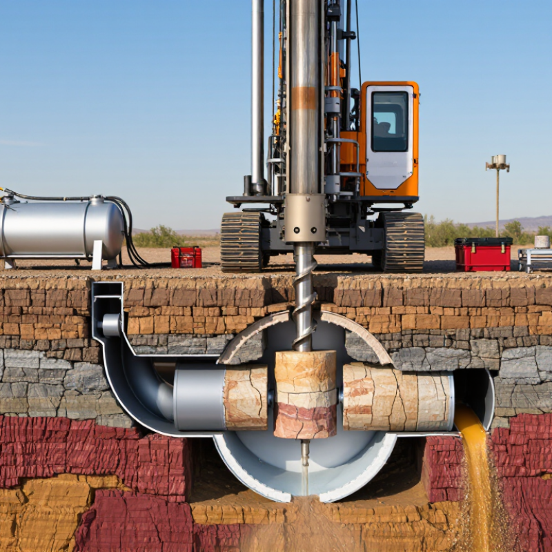
A rock core drill is a machine designed to recover an intact cylinder of rock from below the surface. Its main use is investigation, not simply making a hole. A hollow bit rotates against the formation, while drilling fluid cools the cutting surface and carries fragments upward. Inside the bit, a core barrel captures the solid sample. Technicians then lift the barrel, often through a wireline system, and examine the core for minerals, fractures, strength, and water-bearing zones.
Mining companies use core drilling to estimate ore continuity before excavation begins. Geological teams record recovery, rock quality designation, alteration, and structural angles. Civil engineers use the same method for tunnels, dams, bridges, and deep foundations. According to S&P Global Market Intelligence’s World Exploration Trends 2024, global non-ferrous exploration spending reached about US$12.8 billion in 2023. That investment shows why reliable subsurface samples matter, although exploration budgets do not guarantee a discovery. The USGS Mineral Commodity Summaries 2024 also identifies many minerals as essential to modern industry, increasing pressure for better geological information.
The process is precise, but never perfect. A fractured zone may wash away. Drilling fluid can hide weak material. Operators must control rotation speed, feed pressure, and fluid flow for each rock type. A careless setup can produce a polished core that misrepresents the ground. That risk is easy to underestimate. Core logs therefore need photographs, depth checks, recovery calculations, and independent review before engineering decisions are made.
A rock core drill is built around several tightly matched components. The power unit turns the drill string, while the feed frame pushes it into the rock at a controlled rate. A hydraulic or electric drive supplies torque, but torque alone is not enough. The control panel must balance rotation speed, feed pressure, and flushing flow. Otherwise, the bit can glaze, overheat, or fracture the core.
The drill string transfers force through connected rods. Inside it, the core barrel captures an unbroken rock cylinder. A swivel head helps the inner tube remain stable while the outer tube rotates. At the front, the diamond-impregnated bit cuts the formation, and drilling fluid carries fine debris away. Standard core sizes show the engineering scale: ASTM D2113 commonly identifies NQ core at about 47.6 mm, HQ at 63.5 mm, and PQ at 85.0 mm. ISO 22475-1 also stresses controlled sampling and reliable core recovery. These dimensions are not cosmetic; they affect sample strength, handling, and geological interpretation.
A pump, water tank, valves, and return lines complete the circulation system. According to the International Energy Agency’s Global Critical Minerals Outlook 2024, mineral supply chains face growing pressure from exploration and development demand. That pressure makes dependable sampling more valuable. Yet field conditions remain imperfect. Bent rods, worn seals, and uneven ground can distort results. Experienced crews inspect thread wear, monitor pressure changes, and record recovery length after every run. Small omissions still happen, even on careful sites.
A rock core drill uses a rotating diamond bit to cut a cylindrical sample from solid rock. The core barrel captures the sample, while drill rods transfer rotation and pressure from the surface to the bit. The feed system controls drilling force, and drilling fluid cools the bit, removes rock cuttings, and stabilizes the borehole.
The chart shows common DCDMA wireline core sizes and their nominal recovered core diameters. AQ, BQ, NQ, HQ, and PQ core barrels produce progressively larger samples for geological, mining, and engineering analysis.
A rock core drill is a machine designed to remove a solid, cylindrical sample from bedrock. Unlike a standard drilling tool, it preserves the rock’s layers, fractures, and mineral changes for examination.
The process begins with a site survey. Technicians check the drilling position, ground stability, and expected rock type. They secure the drill frame and choose a diamond-tipped core bit. Water flows through the drill string to cool the bit and carry cuttings away. It also reduces airborne dust.
The operator then starts slow rotation and applies steady downward pressure. The bit cuts an annular path, leaving a rock cylinder inside the core barrel. Pressure must remain controlled. Too much force can crack the sample or damage the bit. Too little force wastes time.
When the barrel reaches its capacity, the operator stops rotation and retrieves it with a lifting tool. The core is removed carefully and placed in a labeled tray. Technicians record depth, recovery length, rock color, fractures, and moisture. They may photograph each section before laboratory testing.
Not every run produces a perfect core. Broken ground can create gaps, and clay may block the barrel. Experienced crews adjust speed, water flow, and pressure after examining each recovery. That judgment matters. A clean sample is useful, but an honest record of poor recovery is useful too.
A rock core drill cuts an annular path through the ground and lifts a cylindrical sample. Its performance depends less on machine power than on rock behavior. The FHWA Rock Slopes Reference Manual, NHI-10-290, classifies intact rock below 1 MPa as extremely weak and above 250 MPa as extremely strong. Strong granite may cut slowly, while weak shale can collapse around the barrel. Hard quartz also accelerates bit wear. Softer claystone may clog the core barrel instead.
Fractures create another problem. The ISRM Suggested Methods report rates rock quality from 0–25% RQD as very poor and 90–100% as excellent. Low-RQD rock often produces broken pieces, lost recovery, and unstable boreholes. Water pressure can wash fines away or reduce wall stability. Dry holes may create dust and overheating. Inclined drilling adds gravity effects, especially when the core is already fractured. These conditions change feed pressure, rotation speed, flushing volume, and expected recovery. A neat drilling model can still fail in the first three metres.
Tips: Check UCS, abrasivity, weathering, RQD, and groundwater before selecting operating settings. Use slower feed pressure in fractured rock. Increase flushing carefully in weak, water-sensitive formations. Record every run, including depth, penetration time, core loss, and fracture condition. Field judgment matters, but it should be documented. The first plan is rarely perfect. Geological uncertainty should remain visible, not hidden in a smooth report.
| Rock Type | Typical Mohs Hardness | Typical UCS Range | Abrasivity | Recommended Core Bit | Expected Drilling Behavior | Key Performance Considerations |
|---|---|---|---|---|---|---|
| Shale | 2–4 | 10–100 MPa | Low to Medium | Diamond-impregnated bit with effective water circulation | Generally easy to penetrate, but core may split, crumble, or swell when wet. | Use careful feed pressure and high-quality core barrels. Reduce water flow where clay swelling or washout is a concern. |
| Limestone | 3–4 | 30–150 MPa | Medium | Surface-set or impregnated diamond bit, selected according to hardness and fractures | Usually drills efficiently. Cavities, bedding planes, and solution channels can cause sudden loss of resistance. | Control rotation and feed when voids are encountered. Maintain sufficient flushing to remove cuttings without eroding weak zones. |
| Sandstone | 4–7 | 20–150 MPa | Medium to High | Diamond-impregnated bit with strong matrix retention | Performance varies widely with cementation. Weak sandstone may produce loose or broken core, while quartz-rich sandstone can be highly abrasive. | Use stable borehole support and adequate flushing. Reduce bit pressure if the formation is friable or poorly cemented. |
| Marble | 3–5 | 50–200 MPa | Medium | Diamond bit suited to crystalline carbonate rock | Normally cuts smoothly, but coarse crystals and foliation may cause variable wear and localized core breaks. | Keep the bit properly dressed and use consistent water flow. Avoid excessive feed pressure across foliation or altered zones. |
| Granite | 6–7 | 100–250 MPa | High | Diamond-impregnated bit with a matrix matched to the rock abrasivity | Slow to moderate penetration with high torque and substantial bit wear. Quartz content commonly increases abrasion. | Maintain adequate cooling and cuttings removal. Excessive pressure can polish the diamonds, increase torque, and reduce penetration. |
| Basalt | 5–6 | 100–300 MPa | Medium to High | Diamond-impregnated bit with strong impact resistance | Dense, fine-grained basalt can require high torque. Vesicles, alteration, and flow contacts may create broken or irregular core. | Use stable operating parameters and inspect the core barrel frequently. Adapt the bit matrix when alternating between hard fresh rock and altered zones. |
| Quartzite | 7 | 150–300 MPa | Very High | Highly wear-resistant diamond-impregnated bit with appropriate diamond concentration | Typically produces low penetration rates and rapid abrasive wear, especially when the rock is massive and intact. | Use controlled feed pressure, sufficient flushing, and frequent checks for matrix glazing or reduced water flow. |
| Weathered or Altered Rock | Variable | Usually lower than fresh rock | Variable | Bit and barrel configuration selected for mixed ground | Penetration may be fast, but core recovery can be poor because of clay, open fractures, decomposed minerals, or unstable walls. | Use a core barrel designed for fractured ground, reduce vibration, and maintain borehole stability with suitable fluid management. |
| How a rock core drill works: A hollow drill bit rotates against the formation while axial feed force and drilling fluid remove cuttings, cool the bit, stabilize the borehole, and carry a cylindrical rock sample into the core barrel. Performance depends on rock strength, hardness, mineral composition, abrasivity, fractures, water conditions, bit design, rotation speed, feed pressure, and flushing efficiency. UCS values are typical indicative ranges and can vary significantly with mineralogy, porosity, weathering, moisture, and test direction. | ||||||
A rock core drill cuts a cylindrical sample from the ground using a hollow barrel and a diamond-set bit. The recovered core shows changes that drilling chips may hide. Crews lift each section carefully, often with an inner tube and wireline system.
Core samples are placed in labeled boxes, in the exact depth order. Technicians mark run length, recovery, and rock quality designation. They photograph wet and dry surfaces under steady lighting. Logs record color, grain size, fractures, weathering, veins, and broken zones. A small depth mistake can affect later decisions. It happens more easily than many reports admit.
Tips: Keep labels visible. Measure fractured pieces before moving them. Photograph the box before testing. Compare the physical core with drilling notes and geophysical results. Evaluation should combine these records, not rely on one impressive-looking section. Engineers may test strength, density, porosity, or mineral content. They also inspect fracture spacing and orientation. A clean core is not always strong rock. Some weak seams remain hidden inside solid-looking pieces. Field judgment improves with experience, but assumptions still need checking.
It recovers an intact cylinder of rock from beneath the surface. Engineers study minerals, fractures, strength, and water-bearing zones. It investigates ground conditions, not just hole depth.
A hollow diamond-set bit cuts the rock while drilling fluid cools it. The fluid carries fragments upward. An inner core barrel captures the solid cylinder.
Mining teams investigate possible ore continuity before excavation. Civil engineers examine ground for tunnels, dams, bridges, and deep foundations. The sample supports better planning.
Important parts include the power unit, feed frame, drill rods, core barrel, bit, pump, valves, and return lines. A control panel balances speed, pressure, and fluid flow. Small parts matter.
Incorrect settings can glaze the bit, overheat it, or damage the core. Hard and fractured rocks need different control settings. A polished core may misrepresent weak ground.
Workers place sections in labeled boxes, keeping the exact depth order. They record run length, recovery, fractures, weathering, veins, and broken zones. Labels should remain visible.
Engineers may test strength, density, porosity, and mineral content. They also examine fracture spacing and direction. A clean-looking core is not always strong rock.
Fractured material may wash away, and drilling fluid can hide weak zones. Bent rods, worn seals, uneven ground, and depth errors also affect results. Mistakes happen.
They should photograph wet and dry cores under steady lighting. Depth checks, recovery calculations, drilling notes, and independent reviews provide useful comparisons. One attractive core section proves little.
A Rock Core Drill is a specialized machine used to obtain cylindrical samples from beneath the ground surface. These core samples help engineers, geologists, and construction teams understand rock strength, layering, fractures, mineral characteristics, and groundwater conditions. The system generally includes a drilling rig, rotating drive, drill rods, core barrel, diamond or carbide cutting bit, circulation system, and support equipment. Together, these components apply controlled rotation and pressure while circulating fluid to cool the bit and remove cuttings.
During drilling, the bit cuts around a solid cylinder of rock, which enters the core barrel as the drill advances. When the barrel is full, the crew retrieves it using an appropriate lifting method, places the core carefully in labeled trays, and records its depth and recovery length. Rock type, hardness, fractures, weathering, drilling angle, fluid choice, and ground stability can all affect performance and sample quality. After retrieval, the core is photographed, logged, measured, and evaluated for features such as recovery percentage, rock quality, discontinuities, and structural changes, providing reliable information for geological investigation and engineering decisions.

KAT DRILLING